
This is a merged information page for Item #127.
View normal product page.
Pololu item #:
127
Brand:
Pololu
Status:
Active

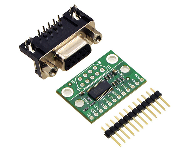
This item is the partial kit version of the 23201a serial adapter. All surface-mount components are assembled; the 0.1″ breakaway male header strip and DB9 connector are included but not soldered.
Alternatives available with variations in these parameter(s): partial kit? Select variant…
 Compare all products in Computer Interface or
  Signal Adapters and Extenders.
 |
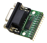
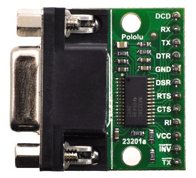
If you want to access all of the features on your computer’s serial port, this serial adapter is for you. The adapter allows you to connect your 3-5.5 V logic circuits to a COM port, which operates on higher and negative voltages (EIA-232, similar to the older RS-232 standard). The adapter is available fully assembled with male header pins facing down for use with prototyping boards and breadboards (as shown to the right), or as a partial kit. The partial kit offers more flexibility if you do not need all of the header pins or if you want to install them on the other side of the board (or not at all).
This adapter is effectively a carrier board for the MAX3238 from Texas Instruments. It distinguishes itself from most competing units through its five drivers and three receivers, which give you access to all eight signal lines on a DB9 connector (the ninth pin is ground). This means that in addition to standard serial communication, your project can also use all of the handshaking lines and status lines. Even if you do not use them for their intended purposes, you might find it convenient to be able to reset your processor using one of the extra lines. A connection detection line gives your project additional options for responding to a physical connection to a serial port. All of this connectivity comes in a compact package that is less than twice the size of the DB9 connector alone.
The first nine pins on the deluxe serial adapter correspond to the same nine pins on a COM port DB9 connector. The additional pins are the logic supply voltage, the serial connection detection pin, and an inverted version of the transmit line (which can be useful if, for instance, you have a positive-edge triggered interrupt that you want to fire in response to the beginning of the start bit). The TX line and RX lines are labeled from the computer’s perspective, so the TX pin has data transmitted by the computer that should be connected to your project’s receive input.
 |
| Pin | Type | Function |
|---|---|---|
| DCD | In | "Data carrier detect" |
| RX | In | Asynchronous serial data receive |
| TX | Out | Asynchronous serial data transmit (idle high) |
| DTR | Out | "Data terminal ready" control output (often used with DSR) |
| GND | Power | Ground |
| DSR | In | "Data set ready" control input (often used with DTR) |
| RTS | Out | "Ready to send" control output (often used with CTS) |
| CTS | In | "Clear to send" control input (often used with RTS) |
| RI | In | "Ring indicator" control input |
| VCC | Power | Logic supply voltage (3 – 5.5 V, externally supplied) |
| INV | Out | Serial port detection pin, high if serial port connected |
| TX | Out | Asynchronous serial data transmit, inverted (idle low) |
| Partial kit?: | Y |
|---|
This DXF drawing shows the locations of all of the board’s holes.
No FAQs available.
No blog posts to show.